Introduction to Gears (What is Gears)
Different Types Of Gears
The gears which are most commonly used for power transmission are :
Spur gears
These gears have their teeth parallel to the center line bf the gear. These are used for transmitting the power between parallel shafts.
 |
| Image by Wikipedia via https://upload.wikimedia.org/wikipedia/commons/thumb/e/e8/Spur_Gear_12mm%2C_18t.svg/1200px-Spur_Gear_12mm%2C_18t.svg.png |
Helical gears
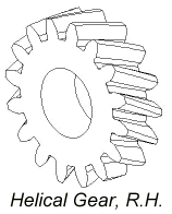
In these gears, the teeth are cut at an angle with the axis of gear, forming the part of helix around the gear. These gears are used for transmitting the power between parallel shafts as well as nonparallel and non-intersecting shafts. These are stronger and quicker in operation, as compared to spur gears. These gears run more smoothly and more quietly at high speeds than spur gears. However, some power is lost because of end thrust, and provision must be made to compensate for this thrust in bearings.
 |
| Image by camnetics via https://camnetics.com/geartrax/FlashHelp/images/helicalgear_rh.gif |
Bevel gears
In these gears the teeth are cut on the conical surface. These are used for connecting the driving shaft and driven shaft whose axes intersect and are generally at right angles. Bevel gears are made with either straight or spiral teeth when the shafts are at right angles and the two bevel gears have the same size, then such a pair of gears is known mitre gears.
 |
| Image by google sites via https://sites.google.com/site/designoftransmissionsystems/_/rsrc/1453465059412/Design-of-Gears/design-of-bevel-gears/Nesdfgsw%20Bitmap%20Imagedszf.jpg?height=174&width=200 |
Worm and worm wheel
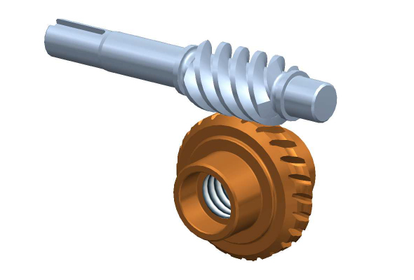
These are used for connecting the driving shaft and driven shaft whose axes are non-parallel and non-inter-secting. Worm gearing is used where a large speed reduction is required.
 |
| Image by kelston via https://www.kelstonactuation.com/imagelibrary/worm-and-wheels.jpg |
Rack and Pinion
Rack gears are straight spur gears with infinite radius. Pinion is a small spur gear. Rack and pinion are used in combination to convert rotary motion into reciprocating motion or reciprocating motion into rotary motion.
 |
| Image by GrabCAD via https://d2t1xqejof9utc.cloudfront.net/screenshots/pics/56cca79555aa57f9b89e4823c76e0c43/large.png |
Internal gears
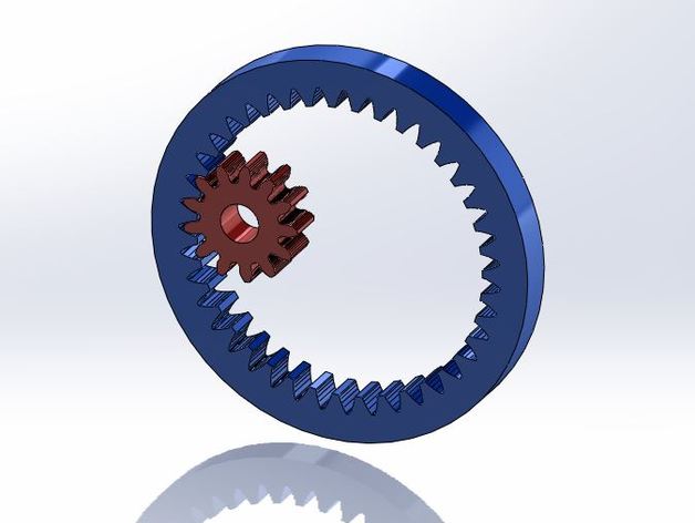
These gears are employed for transmitting the power when the distance between two parallel shafts to be connected is less. Sufficient reduction in speed can be obtained in this case.
 |
| Image by Thingiverse via https://cdn.thingiverse.com/renders/b7/d8/41/ac/9c/Internal__External_Gear_preview_featured.JPG |
Since the involute profile gears are widely used, it is necessary to consider the involute curve in some details.
Gear teeth
The most commonly used forms of gear teeth are as below,
Involute and Cycloidal
The cycloidal gears are not generally used in modern engineering, but used for some crude purposes where heavy and impact loads come on the machine. Involute gears are now almost entirely used for general purpose in precision engineering.
The involute gears also called as straight tooth or spur gears possess the following advantages over the cycloidal gears.
1. The variations in the center distance between two gears have no effect on the velocity ratio between a pair of involute gears.
2. The pressure angle is constant.
3. The involute rack has straight teeth. Thus the complex involute form can be generated by using a relatively simple cutter.
4. All the gears having the same pitch and pressure angle work correctly together,
5. The face and flank of a tooth forms a continuous curve.
Reference - A textbook of METROLOGY by M. Mahajan
Conclusion
info.mechtrekk@gmail.com


0 comments: